Get in touch with us today and our team of imaging professionals will be pleased to assist you.
Synchronize Area-Scan Cameras with PTP in eCapture Pro
Use Precision Time Protocol (PTP) in eCapture Pro to start area-scan cameras from a shared PTP timing reference and keep camera timestamps aligned.
This topic describes a typical workflow for configuring and verifying PTP synchronization for area-scan cameras in eCapture Pro.
What PTP does
PTP synchronizes the clocks on connected cameras so they can use a common time reference.
A PTP grandmaster clock is the timing source that provides the shared time reference for the synchronized cameras.
In eCapture Pro, PTP works together with the camera acquisition settings, trigger settings, and frame-rate settings. PTP synchronization is applied when the cameras start streaming.
Note: When you start cameras with PTP enabled, eCapture Pro sets the PTP acquisition gate time for the cameras. Do not manually configure PTP acquisition gate time for this workflow unless Emergent support instructs you to do so.
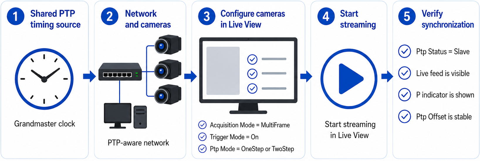
Figure 1: How PTP synchronization works for area-scan cameras in eCapture Pro
PTP use cases
PTP supports different timing workflows.
- PTP frame synchronization: Area-scan cameras start acquisition from a shared PTP-based timing reference. If you also need frames to stay aligned by frame number, use the same frame rate on all cameras in the synchronized group.
- PTP timestamping: Cameras use synchronized clocks to timestamp frames, while another mechanism, such as hardware triggering, controls image acquisition.
This topic focuses on PTP frame synchronization for area-scan cameras in eCapture Pro.
Note: Some systems use hardware triggering to control image acquisition and PTP to provide synchronized timestamps. In that workflow, the hardware trigger determines when frames are captured, while PTP keeps camera timestamps aligned. This topic does not describe that workflow.
Example setup
This procedure assumes a system with:
- One host computer running eCapture Pro.
- One or more supported NICs.
- Two or more area-scan cameras.
- A PTP timing source that all synchronized cameras can use.
This example uses a group of area-scan cameras configured with the same PTP, acquisition, trigger, and frame-rate settings so frames stay aligned by frame number.
Before you begin
Before you configure PTP synchronization, complete these tasks:
- Add the local server, NICs, and cameras in System view.
- Confirm that the cameras appear in Live View.
- Confirm that each camera in the synchronized group supports the selected PTP mode.
- Stop streaming before you configure camera parameter values.
Important: To keep frames aligned by frame number, configure the same Frame Rate on all area-scan cameras in the synchronized group. Cameras with different frame rates can still be PTP-synchronized and can start acquisition at the same PTP time, but their frame numbers will not stay aligned. For example, frame 10 from one camera might not have the same timestamp as frame 10 from another camera.
Note: After you change image format, resolution, pixel format, or related camera settings, recheck the frame rate on each camera in the synchronized group.
For more information, see the Software Quick Start Guide.
Configure the PTP and acquisition settings
Configure the same PTP, acquisition, trigger, and frame-rate settings on each area-scan camera in the synchronized group.
- In Live View, select the first area-scan camera in the synchronized group.
- In the Parameters panel, set Acquisition Mode to MultiFrame.
- Set Trigger Mode to On.
- Set Trigger Source to Software.
- Set Acquisition Frame Count to 1.
- Set Ptp Mode to the mode required by the PTP timing source:
- Use OneStep if the PTP timing source sends one-step PTP packets.
- Use TwoStep if the PTP timing source sends two-step PTP packets.
- To keep frames aligned by frame number, set the same Frame Rate on each area-scan camera in the synchronized group.
- Apply the same PTP, acquisition, trigger, and frame-rate settings to each area-scan camera in the synchronized group. If appropriate, broadcast the required parameter values to the other cameras.
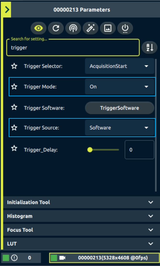
Figure 2: Trigger Mode and Trigger Source settings in the LIve View Parameters panel
Verify PTP synchronization in Live View
After you configure the cameras, start streaming in Live View to verify that PTP synchronization is working.
- In Live View, select each camera in the synchronized group.
- Confirm that each camera reports Ptp Status = Slave.
Note: If Ptp Status does not update in the Parameters panel, click the refresh button to poll the camera again. - Start streaming on the cameras.
- Confirm that each camera shows a live feed.
- Confirm that the camera’s green status square in Live View shows P.
- Confirm that Ptp Offset is stable and acceptable for the application.
- In Status view, you can monitor PTP offsets and configure error and warning levels for them.
- If you configured the cameras with the same frame rate, confirm that frames stay aligned by frame number.
Note: The P indicator shows that the camera started streaming with PTP. Use Ptp Status, Ptp Offset, the live feed, and any available frame timing information to verify synchronization. Do not rely only on the status indicator.
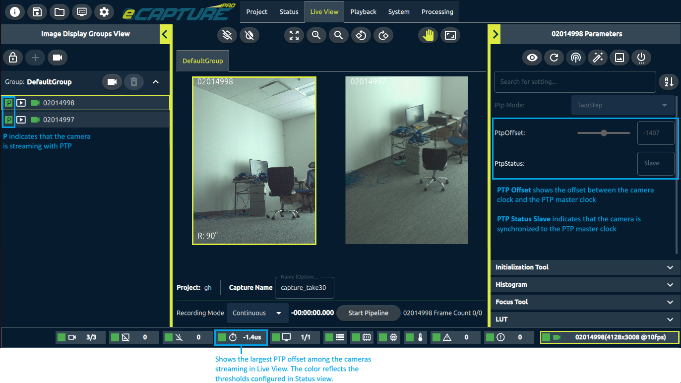
Figure 3: Live View shows information about PTP synchronization
Troubleshooting
See also
Get in touch with us today and our team of imaging professionals will be pleased to assist you.