Get in touch with us today and our team of imaging professionals will be pleased to assist you.
Processing Images from Emergent Vision Cameras
After you configure the hardware in System View, use Processing View to configure a pipeline that processes images from Emergent Vision cameras.
eCapture Pro provides built-in processing tasks for saving raw images, compressing streams with NVENC, and displaying processed images in Live View. You can also add custom processing plugins created with eSDK Pro.
In Processing View, use the Processing Actions section to select a server and add processing tasks or plugins. Use the graph panel to connect pipeline nodes. When you select one or more nodes in the graph, the Selected Nodes section appears and shows the available settings and actions for those nodes.
For an introduction to Processing View, see The eCapture Pro Processing View.
Before You Start
Before you create a processing pipeline, complete the first two Recording Workflow procedures in eCapture Pro:
- Add or Load a Project in Project View.
- Configure the System Hardware in System View.
Processing Pipeline Troubleshooting
If a pipeline node has alerts, the pipeline will not run until you resolve the issues or disable the node.
To disable a node, select it in the graph, and then use the toggle switch in the Selected Nodes section.
Saving Images from Cameras to Disks
You can record camera images by saving raw, uncompressed image data directly to disk. This is the simplest processing pipeline in eCapture Pro's Processing View. It starts with a camera node and ends with a raw saving node.
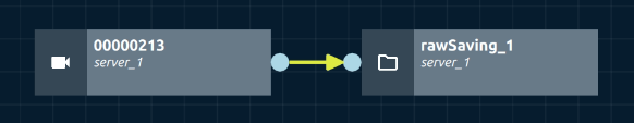
Figure 1: Raw Saving pipeline in Processing View
- Select the Processing tab.
- In the Processing Actions panel, select the server that will run the pipeline. The camera node or nodes that are connected to the server in System View appear in the graph.
- Click the background of the graph to ensure no nodes are selected.
- In the Add Processing Tasks section, click the add icon (+) next to Raw Saving. A Raw Saving node appears in the graph.
- In the graph, select the Raw Saving node. The Selected Nodes section appears in the Processing Actions panel.
- In Selected Nodes, configure the Raw Saving settings:
- Server
- CPU Core
- Direct IO
- Multi-Storage
- Storage Device
- In the graph, connect the camera node or nodes to the Raw Saving node.
Note: The Storage Device list contains the storage devices that you added earlier in System View.
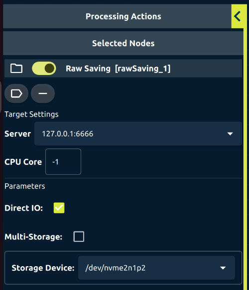
Figure 2: Selected Nodes showing settings for a Raw Saving node in Processing View
Compressing and Saving Images
Use this procedure to compress image streams with NVIDIA’s H.264 or H.265 encoder. The NVENC Compression node helps reduce storage needs and makes it easier to record or stream high-speed camera data.
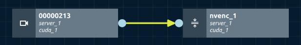
Figure 3: NVENC Compression pipeline in Processing View
- Select the Processing tab.
- In the Processing Actions section, select the server that will run the pipeline.
- In the Add Processing Tasks section, click the add icon (+) next to NVENC Compression. An NVENC Compression node appears in the graph.
- In the graph, select the NVENC Compression node. The Selected Nodes section appears in the Processing Actions panel.
- In Selected Nodes, configure the NVENC Compression settings:
- Server
- Host GPU
- CPU Core
- Pixel Format
- Width
- Height
- Codec
- Bitrate (Kbps)
- Output Framerate
- Output type
- Storage Device when Output type is set to Disk
- Ensure the settings are compatible with the camera parameters configured on Live View.
- In the graph, connect the camera node or nodes to the NVENC Compression node.
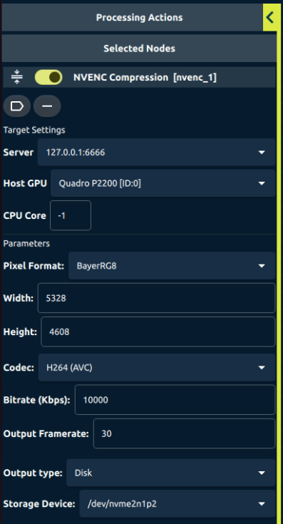
Figure 4: Selected Nodes showing settings for an NVENC Compression node in Processing View
Displaying Processed Images
Use this procedure to display images that have been processed by a custom plugin. The Image Display node lets you view the results of real-time processing, such as filtering or enhancement, in the Live View tab.
The following figure shows a processed-image display pipeline that includes the Cuda Brightness plugin.
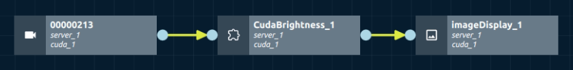
Figure 5: Processed-image display pipeline in Processing View
- Select the Processing tab.
- In the Processing Actions section, select the server that will run the pipeline.
- In the Add Plugins section, click the add icon (+) next to Cuda Brightness. A Cuda Brightness node appears in the graph.
- In the graph, select the Cuda Brightness node. The Selected Nodes section appears in the Processing Actions panel.
- In Selected Nodes, configure the Cuda Brightness settings:
- Server
- Host GPU
- CPU Core
- Brightness Factor
- In the Add Processing Tasks section, click the add icon (+) next to Image Display. An Image Display node appears in the graph.
- In the graph, select the Image Display node. The Selected Nodes section appears in the Processing Actions panel.
- In Selected Nodes, review the Image Display settings.
- In the graph, connect the camera node or nodes to the Cuda Brightness node. Then connect the Cuda Brightness node to the Image Display node.
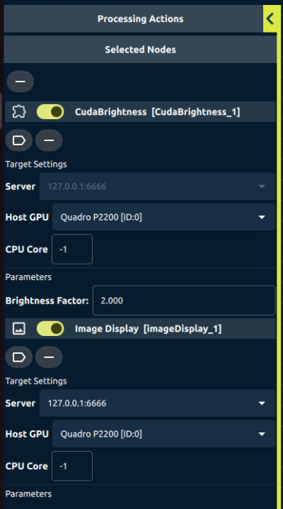
Figure 6: Selected Nodes showing selected Cuda Brightness and Image Display nodes in Processing View
Get in touch with us today and our team of imaging professionals will be pleased to assist you.