Get in touch with us today and our team of imaging professionals will be pleased to assist you.
HE (Eros) Power Accessories
This document from Emergent Vision Technologies describes HE (Eros) camera power accessories, including regulated 12 VDC power supplies and GPIO breakout cables. These accessories work with HE high-speed cameras, provide reliable power delivery, and offer convenient access to GPIO signals. Selected models also expose control lines for EF/RF lens adapters (EF = Canon EF mount, RF = Canon RF mount).
The sections below summarize the accessories, list technical specifications, and provide pinout tables to support system integration.
Feature Matrix
Notes
- All GPIO breakouts use flying-lead wires.
- Flying-lead length: 200 mm.
- PoE accessories do not contain a power supply; the camera receives power over Ethernet from the PoE network equipment.
See also: Camera GPIO Ports and Schematics
HE PWR 24W: Standard Power Supply
Provides regulated 12 VDC / 24 W to HE cameras through an M8 connector. No GPIO signals are exposed.
M8 Connector Pinout and Lead Assignments
Note: This accessory supplies power only. Pins 2–7 are unused, and no GPIO lines, flying leads, or EF/RF connections are exposed.
Specifications
- Output: 12 VDC, 24 W, 2 A
- Provides power: Yes
- Exposed lines: None
- Connector: M8×1 male
- Cable length: 2.0 m
- Flying leads: No

Figure 1: HE Standard Power Supply
HE PWR BREAK: Power Supply with GPIO Breakout
Provides 12 VDC / 24 W to HE cameras and exposes GPIO and power lines on flying leads.
M8 Connector Pinout and Lead Assignments
Note: Pin 8 (GND) is connected both to the camera and to a flying lead.
Specifications
- Output: 12 VDC, 24 W, 2 A
- Provides power: Yes
- Exposed lines: TTL_IN, TTL_OUT, OPTO_IN, OPTO_OUT, VDD_OUT +12 V, grounds
- Connector: M8×1 male
- Cable length: 2.0 m
- Flying-lead length: 200 mm
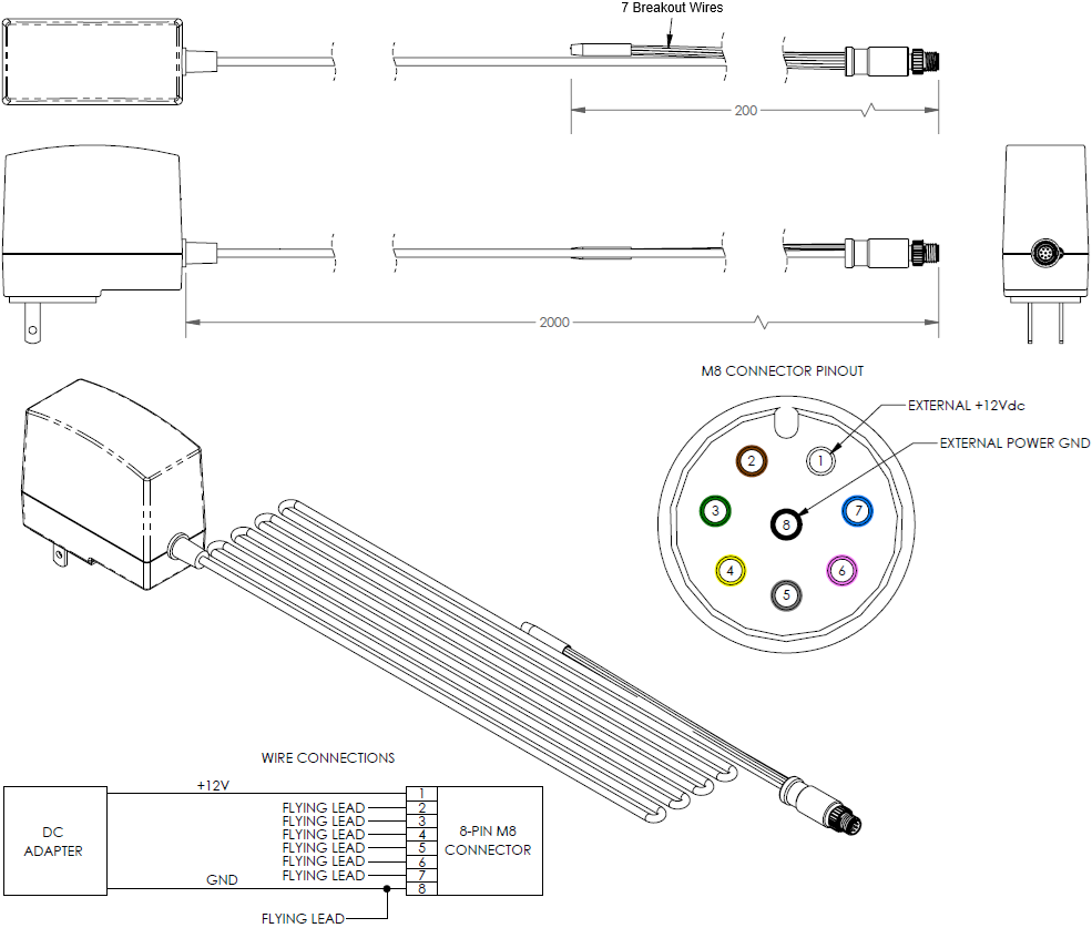
Figure 2: HE Power Supply with GPIO Breakout
HE PWR and EF/RF BREAK: Power and EF/RF Breakout
Provides 12 VDC / 24 W and exposes GPIO plus EF/RF lens control on flying leads.
M8 Connector Pinout and Lead Assignments
Notes
- Pin 6 is connected to the camera and also brought out as a flying lead.
- Pin 8 is connected to the camera, the EF/RF lens connector, and a flying lead.
Specifications
- Output: 12 VDC, 24 W, 2 A
- Provides power: Yes
- Exposed lines: pins 2, 3, 6, 7, 8 (GPIO/EF-RF per above)
- Connector: M8×1 male
- Cable length: 2.0 m
- Flying-lead length: 200 mm
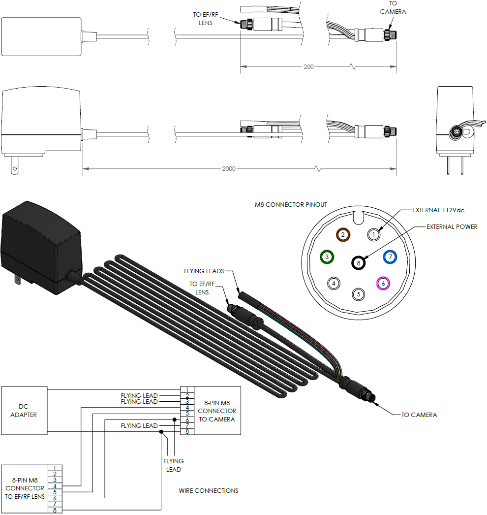
Figure 3: HE Power Supply with GPIO and EF/RF Lens Breakouts
HE PoE EF/RF BREAK: EF/RF Breakout for PoE
Exposes EF/RF lens control lines for PoE-powered HE cameras.
M8 Connector Pinout and Lead Assignments
Notes: Pins 6 and 8 are connected to the camera and also brought out as a flying lead.
Specifications
- Provides power: Yes (via PoE)
- Exposed lines: pins 2, 3, 6, 7, 8
- Connector: M8×1 male
- Cable length: 2.0 m
- Flying-lead length: 200 mm

Figure 4: HE Cable with GPIO and EF/RF Lens Breakouts for PoE-Powered Cameras
HE GPIO BREAK: GPIO Breakout Cable
Breaks out all 8 pins of the M8 connector for integration flexibility. Can also be used to supply external power.
M8 Connector Pinout and Lead Assignments
Notes
- With PoE, leave pin 1 floating.
- Without PoE, use pin 1 with an external 12 V DIN-rail supply.
- For SFP+ models, pin 1 must supply 12 V.
Specifications
- Provides power: No
- Exposed lines: all GPIO, +12 V, and grounds
- Connector: M8×1 male
- Cable length: 2.0 m
- Flying-lead length: 200 mm
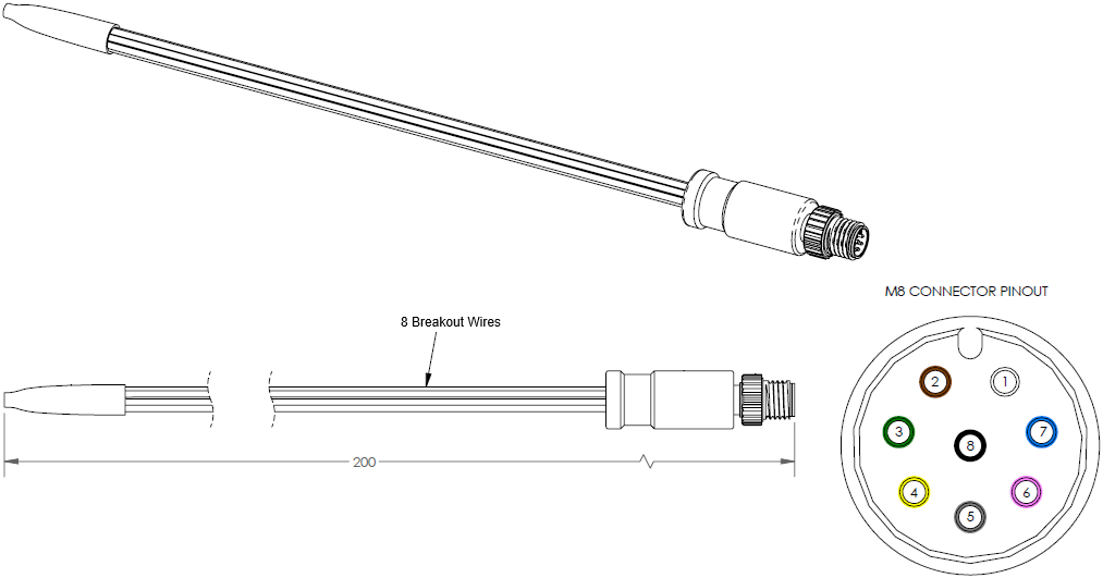
Figure 5: HE GPIO Breakout Cable
Get in touch with us today and our team of imaging professionals will be pleased to assist you.