Get in touch with us today and our team of imaging professionals will be pleased to assist you.
Pixel Processing Stages and Related Camera Features
Image data from an Emergent camera passes from the image sensor through a fixed sequence of FPGA processing stages before leaving the camera through the camera data interface. This topic shows the processing order for area-scan and line-scan cameras and identifies the customer-accessible camera features associated with each stage.
Area-scan and line-scan cameras use different processing stages. The available features depend on the camera model and configuration.
Note: This topic describes the pixel-processing path. It does not cover exposure, triggering, frame-rate or line-rate control, or other image-acquisition functions.
Pixel processing in area-scan cameras
Image data from an Emergent area-scan camera passes from the image sensor through a fixed sequence of FPGA processing stages before leaving the camera through the camera data interface.
White balance and color correction matrix processing apply only to color cameras.
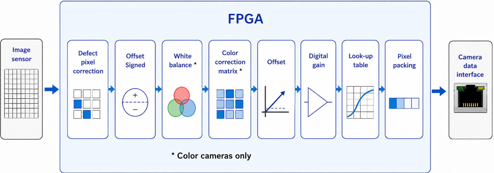
Figure 1: Pixel processing stages in area-scan camera FPGAs
The diagram shows the order in which image data passes from the image sensor through the FPGA processing stages in area-scan cameras from left to right. It does not indicate that every related feature is available or enabled on every camera. Feature availability depends on the camera model and configuration.
The FPGA processing order is fixed and cannot be changed. Because each stage receives the output of the preceding stage, changing an earlier feature can affect the input and result of later processing.
The following table identifies the configurable camera features related to each stage in area-scan cameras.
Table 1: Pixel processing stages and related features in area-scan cameras
Pixel processing in line-scan cameras
Image data from an Emergent line-scan camera passes from the image sensor through a separate, fixed sequence of FPGA processing stages before leaving the camera through the camera data interface.
Spatial correction applies only to tri-linear line-scan cameras. White balance and color correction matrix processing apply only to color cameras.
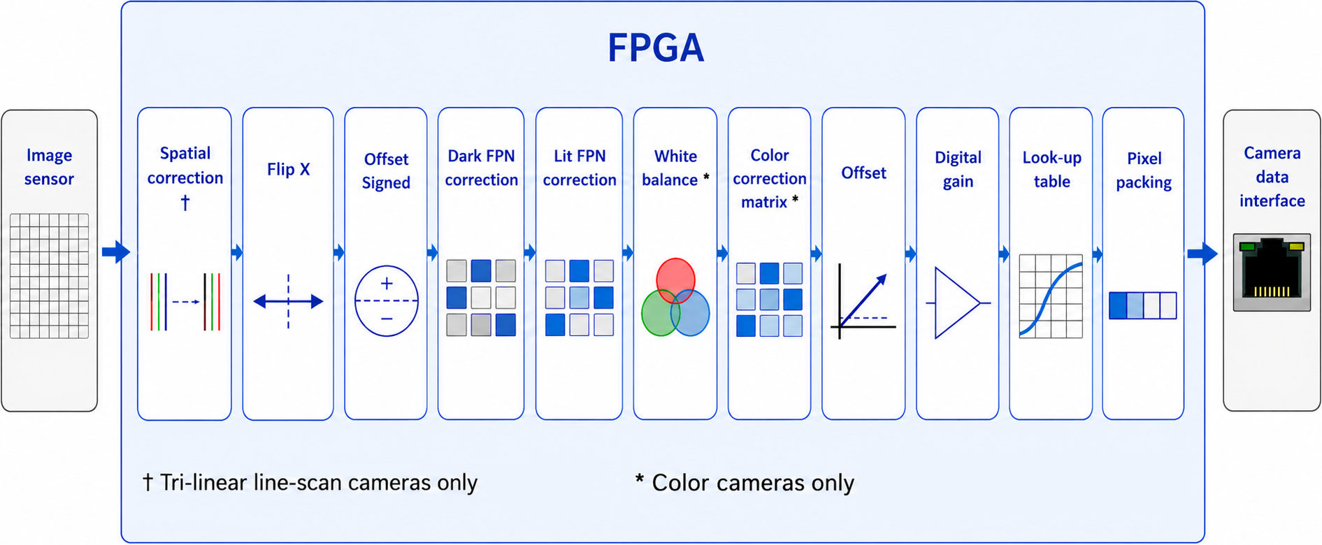
Figure 2: Pixel processing stages in line-scan camera FPGAs
The diagram shows the order in which image data passes from the image sensor through the FPGA processing stages in line-scan cameras from left to right. Spatial correction applies only to tri-linear line-scan cameras, and the color-processing stages apply only to color cameras.
The FPGA processing order is fixed and cannot be changed. Because each stage receives the output of the preceding stage, changing an earlier feature can affect the input and result of later processing.
The following table identifies the configurable camera features related to each stage in line-scan cameras.
Table 2: Pixel processing stages and related features in line-scan cameras
See also
For information about other types of camera features, see Camera Features Overview.
Get in touch with us today and our team of imaging professionals will be pleased to assist you.